Mark Vision Trim Monitoring Device Model
MRV-021
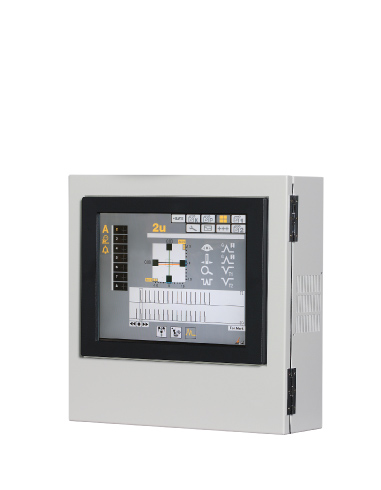
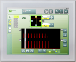
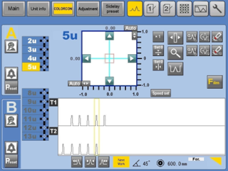
To display trim marks quickly and accurately, MarkVision is intuitively operated via a touch panel.
■Features
- Mark Vision makes it easy for anyone to check the orientation, which tends to rely on experienced people.
- All units can be synchronized in one place. *line shaft printing machine
- Mark Vision allows you to quickly fine-tune your orientation over time from the image.
- Adjusting and checking twists is also possible quickly by adopting two camera units.
Simple operability
Contribute when printing starts
■Specifications
| Power supply voltage | AC100V ±10% 5A or AC200~240V ±10% 3A | |
|---|---|---|
| Main unit | Monitor | 7 inches *Optional 10 inches ・ 15 inches |
| Operation specifications | Touch panel screen operation (up and down operation, brightness adjustment, etc) |
|
| Moving specifications (up and down movement) |
small button: ±1P, large button: ±10P | |
| Vertical resolution (up and down movement) |
Small button 1P Printing circumference [mm] / 1000, 1024, 2000, 2048(by pulse number) |
|
| Encoder input method | Line driver Voltage input (5V) 1000P, 1024P, 2000P, 2048P |
|
| Camera unit | Number of pixels | 2 megapixels |
| Lens | Fixed magnification lens | |
| Zoom function | Digital zoom Vertical: about 2 x Horizontal: about 2 x |
|
| Paper viewing angle (vertical× horizontal) |
Maximum viewing angle 26×14 [mm] Minimum viewing angle 13×7.5 [mm] |
|
| Distance between papers (vertical× horizontal) |
10[mm]±2 | |
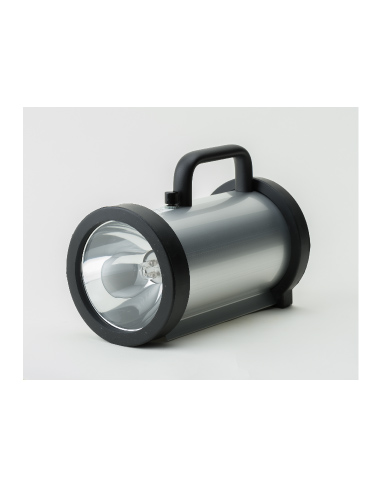
| Light source | LED 1 row 9 pieces ×2 rows (Total 18 pieces) | |
| Brightness adjustment | Adjustable via touch panel | |
| Focus adjustment | Adjustable via touch panel or camera adjustment mechanism | |
| Adaptive printing speed(Web speed) | Rotational speed: Maximum 800 [RPM] | |
■Equipment configuration
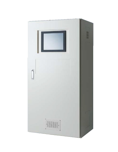
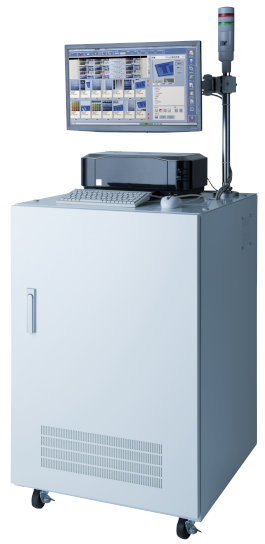
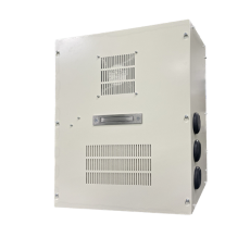
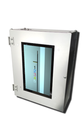
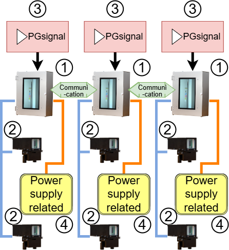
*Multiple units can be installed- ① monitor box (main unit)
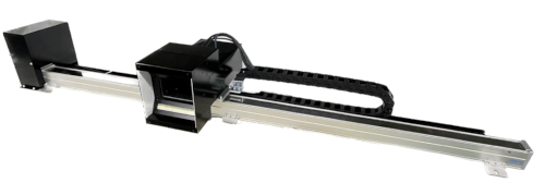
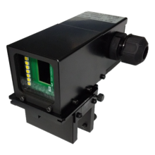
- ② camera unit (BOX)
-
③ PG signal (mechanical synchronization signal)
Obtained from COLORCON or printing press. -
④ power related
Breaker
Noise filter
Switching power supply - ※ A milky white detection panel is required separately on the back of the equipment.
■Function description
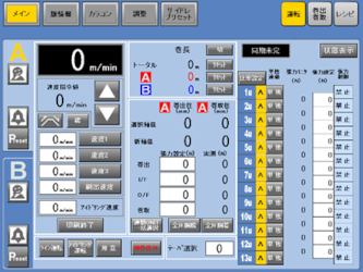
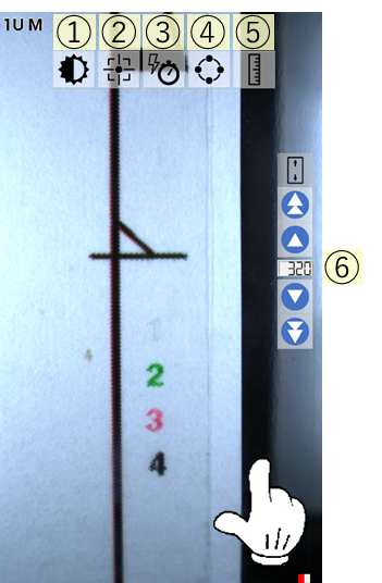
Touch panel operation
- ① Brightness adjustment
Adjust brightness manually - ② Autofocus function
By selecting the image you want to see, you can automatically focus - ③ Manual sync selection
Manually select the location where you want to view the printed matter - ④ Unit synchronization
When multiple units are installed, other synchronizations are also linked.
※ *Only when installed on a line shaft printing machine - ⑤ Ruler grid line display
Display a ruler or grid-like line on the image and visually check the size - ⑥ Image up/down function
Image up/down operation
Check the alignment of the twist
- If you purchase two camera units, you can check the alignment of the twist.
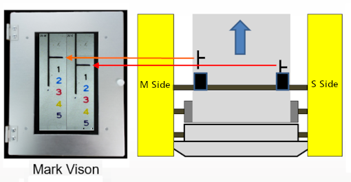
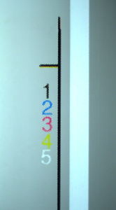
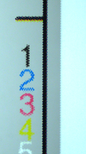
Trim mark image
