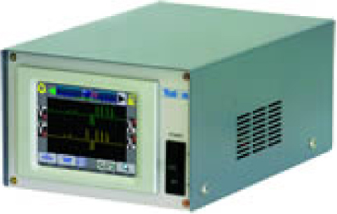
Automatic Cutter Alignment Equipment
Model CR-555M II
This equipment measures and corrects the web cutting position. When the measured discrepancy of the cutting position exceeds the set value, notification is issued by way of an alarm and other means. Options include PIV control circuit.
■Product features
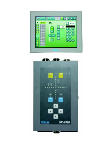
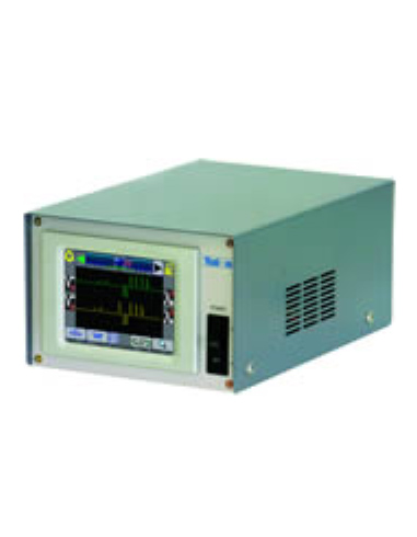
- Easy-to-read waveform display
Signals from the scanning head can be shown on the 5.7-inch color liquid crystal display.
Display of signals for one pitch is possible, making designation of the control gate position easier. - Operation is possible on the touch panel
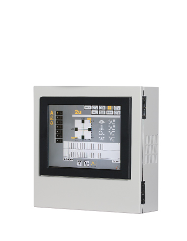
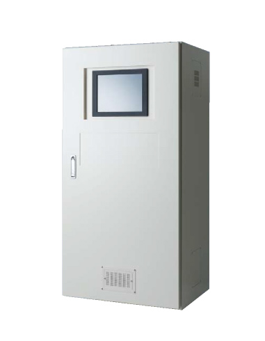
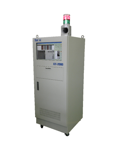
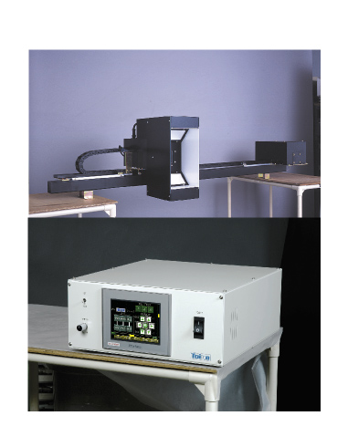
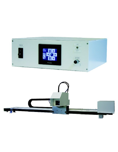
Settings are made on the same screen, after switching from the waveform setting screen. - It is possible to select from two settings to suit the installation location.
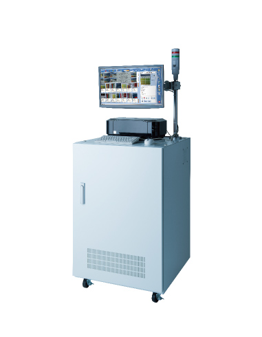
It is possible to choose from the integral main unit/display type and the separately installed display type.
■Specifications and capacities
| Correction mechanism | Compensator roller or differential control Rotary cutter control |
|---|---|
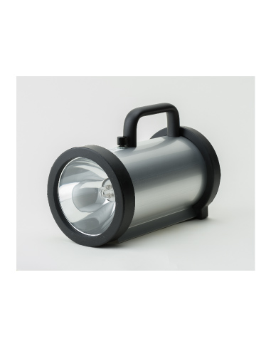
| Detection mechanism | scanning head |
| Detection accuracy | +/-0.01 mm/td> |
| Range of fine adjustment | +/-9.9 mm |
| Colors detected on pitch | visually discernible practical colors |
| Warning set-up value | variable between 0.1 mm and 9.9 mm |
| Power source | AC100V/200V +/- 10% 1φ 50/60 Hz 1 kVA |
| Compatible environment | Temperature: -10°C to +40°C Humidity: 20% to 80%RH (no condensation) |
■Configuration
| Main body of the equipment | one unit |
|---|---|
| Scanning head | one unit |
| Fiber cord | one unit |
| Head relay box | one unit |
| Pulse generator | one unit |
| Options | register motor, two-stage control, additional control |
■Screen configuration
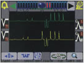 |
Waveform screen This is the screen for displaying waveforms from the scanning head (detector), to display the standard waveform. |
|---|---|
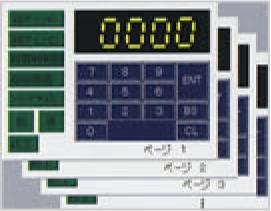 |
Numeric value input screen (set-up screen)
Settings are input using the numeric keypad and finalized after switching pages with the forward and backward switches. ENT: finalization BS: move backward one character CL: clears all characters Other screens for optional functions |
 |
Warning On/Off When the setting is on, warning output is turned on when the limit at which the warning is activated, as set on the other screen, is reached. |
|---|---|
 |
Automatic On/Off When the setting is on, the direction of correction is displayed using the right and left arrows on the error meter below. |
 |
Error meter and plate error switch (display of correction direction) Displacement in the matched waveforms is displayed on the meter. The error can be entered in the positive and negative directions by pressing the meter section |
 |
Waveform reversal switch Reverses the T1 and T2 waveforms |
 |
Waveform amplifier switch Amplifies the T1 and T2 waveforms through four increments |
 |
Gate shifting switch The switch should be turned on when manually setting the gate (the standard position for matching waveforms.) (The setting is made by touching the screen.) |
 |
Mark searching switch The gate position is searched automatically when the switch is pressed. |
 |
Waveform scroll switch The waveform display is rotated through 180 degrees each time the switch is pressed. |
 |
Screen switch The screen is switched from the waveform display screen to the set-up value input screen and others. |
 |
Waveform enlargement switch
The waveform in the vicinity of the current gate position is enlarged and displayed.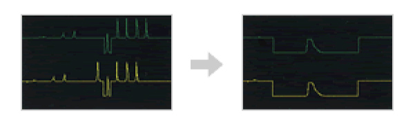 |
※Display of unnecessary switches can be restricted through set-up on another screen.
※The screen design is subject to change without notice.
■System diagram